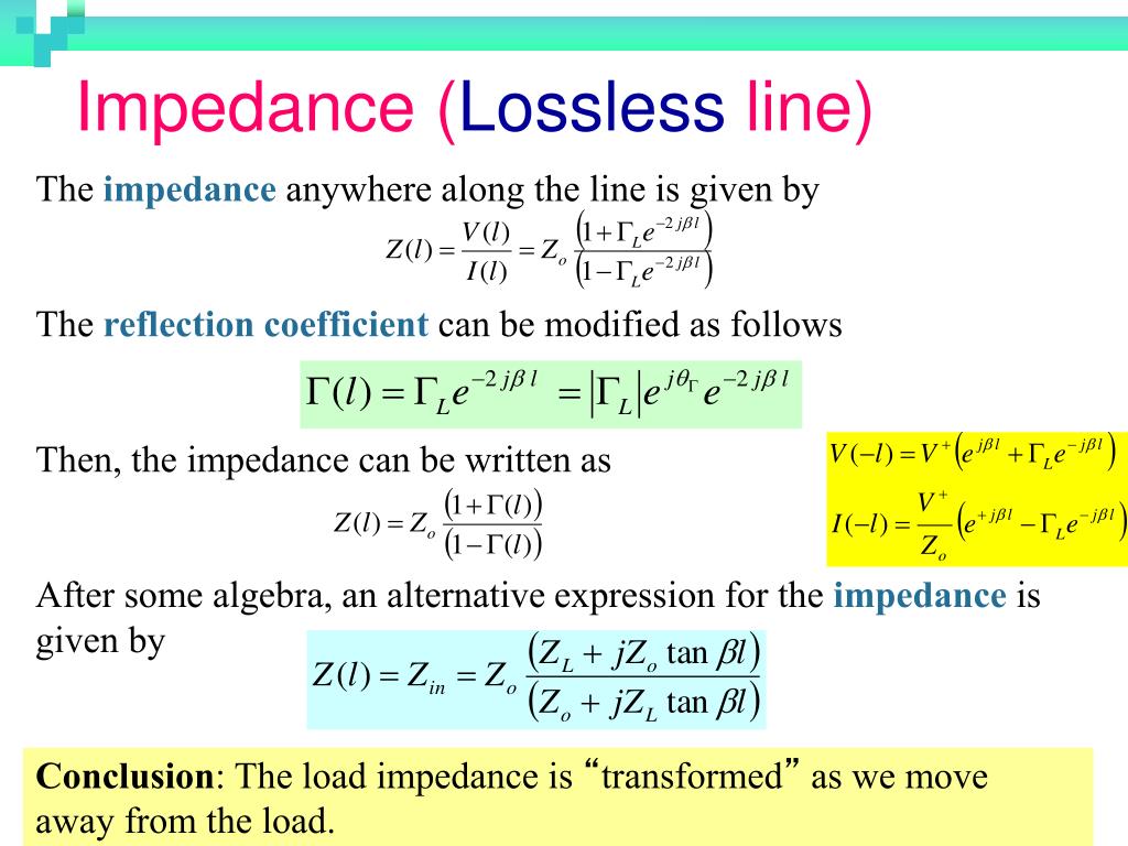


Terminating the line with its characteristic impedance will result in a line that looks infinitely long because there are no reflections coming from the end of the cable. Using the TDR, you will find that the largest reflection in the transmission line occurs at the end of the cable when it is left as an open circuit, because the instrument is actually measuring the very large resistance between signal and ground at the end of the cable. You can also measure characteristic impedance throughout the length of a transmission line using a time-domain reflectometer (TDR) by connecting it to one end of the cable and using it to emit a pulse with a very fast edge rate down the cable and then measuring the reflections caused by any impedance changes in the cable. For this particular cable, we calculate characteristic impedance to be 50.3 Ω. In the above equation is the relative permittivity (dielectric constant) of the material between the two conductors. To calculate the characteristic impedance of the coaxial cable shown above, the following equation can be used: For example, consider the coaxial cable shown in Figure 2. It is therefore easy to calculate their characteristic impedance. Lumped Model of a Very Short Segment of Transmission LineĬables with common geometries such as coaxial cables have very little variation in characteristic impedance across their lengths. Practically speaking, frequency and the per unit resistance, conductance, capacitance, and inductance of a line will determine the ratio of voltage and current, and will thus also define characteristic impedance, which is usually denoted Z o.įigure 1.

Characteristic impedance can be defined along any point on that transmission line as the ratio of a single pair of voltage and current waves at that point in the cable in the absence of all reflections. It will then proceed to elaborate on design considerations for switch products and networks to improve impedance matching in switch systems and minimize signal reflections and power loss.Īny RF transmission line, of which all coaxial cables and switches are a subset, has some characteristic impedance that may or may not be constant over the length of that line. Impedance matching is designing an RF system so that all the source, load, and characteristic impedances match, in order to ensure maximum power transfer and minimum reflected power. This chapter will begin by defining characteristic impedance and the importance of impedance matching in RF switch systems. What properties do switches marketed as ‘RF’ or ‘High Frequency’ have that are not present in those used for lower frequency applications? The answer lies in the careful attention to characteristic impedance throughout the switch design.

Switches designed for higher frequency systems typically have lower channel count than their low-frequency counterparts due to increased relay size and larger isolation (spacing) requirements and can be considerably more expensive. However, the characteristics and design of a switch module that will work for DC measurements versus those of a product best suited for RF systems are vastly different. Switch systems can be used to increase channel count and automate signal routing in test systems ranging from precision DC measurements to RF.


 0 kommentar(er)
